Using water slide decals
Posted on February 21st, 2017
I have tried various methods to finish off pedals but recently I have been using water slide decals to add artwork to pedals. The process is straight forward and can produce fairly good results and is great if you want to use detailed or photo artwork.
I used water slide decal paper that can be used with an ink jet print. This is available in white backed or clear paper and feeds through your printer as normal. If you are using an ink jet printer you will need to spray a number (I used three) of thin coats of lacquer before soaking the paper in water. This should not be required if you are using a laser jet printer.
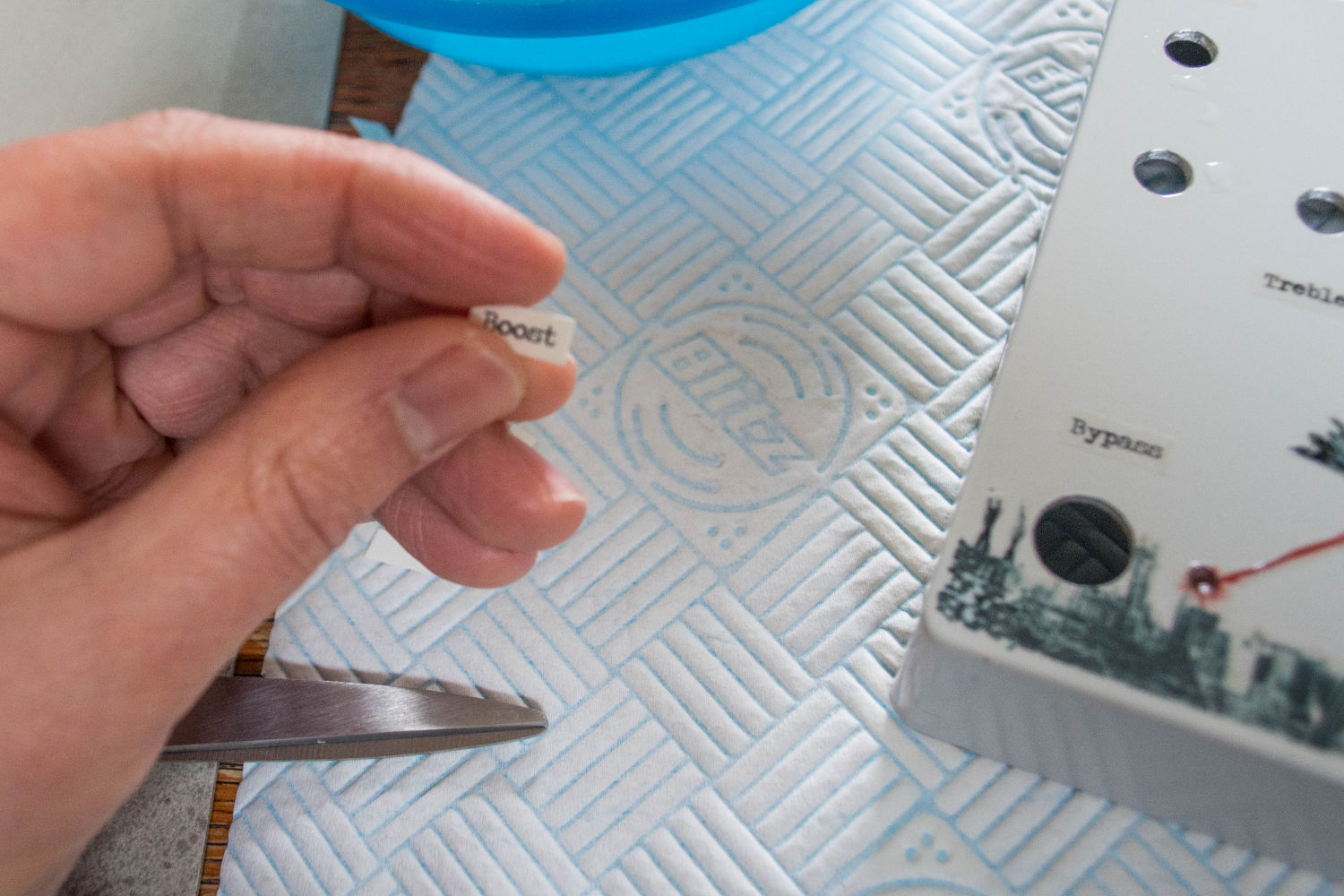
Water slide decal cut out
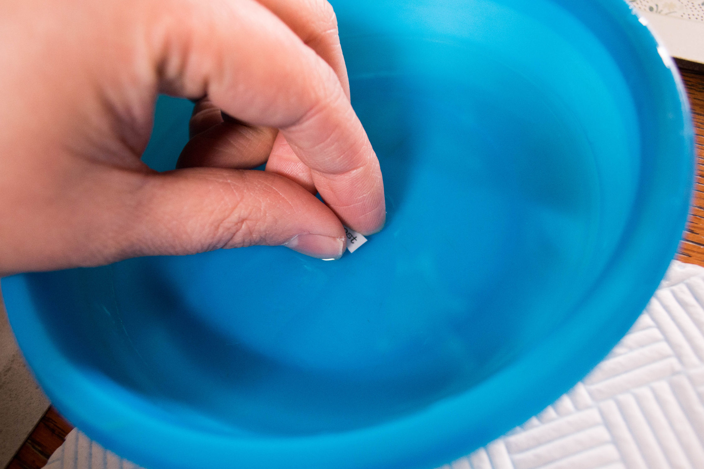
Soaking a water slide decal
Once the lacquer has dried, your decals can be cut out carefully and soaked in water for a few seconds. When the decal has soaked for enough time, you should be able to gentle slide the decal from the paper backing and position it in place on your pedal. To help move the decal around it helps if you place a few drops of water to on the pedal first. Once you have the decal position, a tissue or paper towel can be used to remove excess water. Be careful as it is easy to accidentally move the decal.
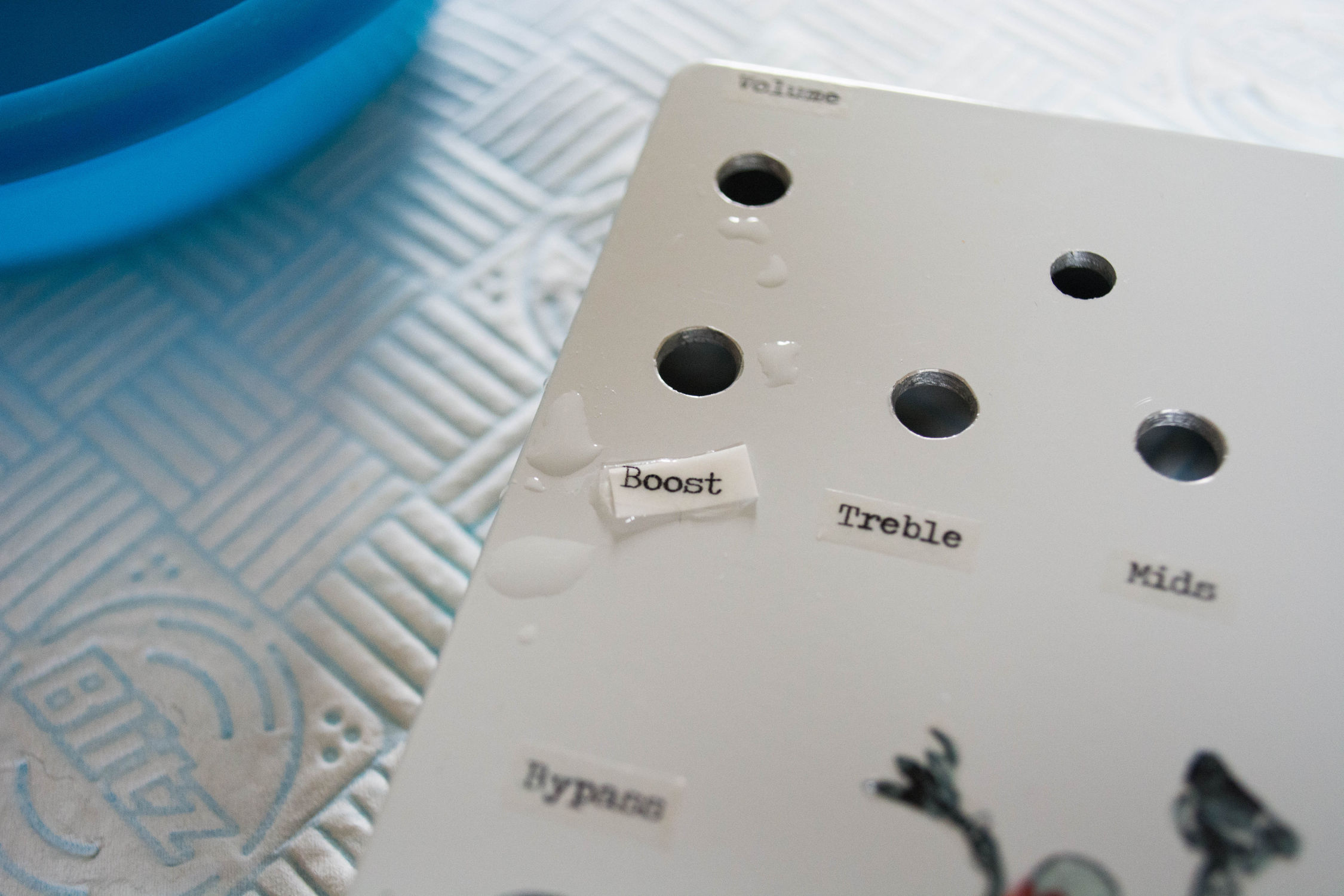
Sliding the water slide decal into place before removing the backing

Excess water can be removed with a tissue or paper towel
I then leave the pedal to dry for a few hours before applying final coats of lacquer. Once finished you can see the edge of the decal when looking closely I need to experiment with different lacquers to see which work best. The lacquer I am using tends to yellow, which shows up the edges quite a bit. I have only used clear decals on light powder coated enclosures as the colours will show up better.

Water slide decals after applying the final lacquer
I leave quite a large border around my decals to make it a bit easier, cutting closer to the design could hide the edges once the final layers of lacquer have been applied.
Be careful when moving the decals around, it can be easy to warp or stretch a decal if you move it too much.
Etching single and double sided PCBs
Posted on December 16th, 2016
This is going to be a quick post about how I etch PCBs and more importantly my recent experience with double sided PCBs. I won’t go into too much detail but I am going to try and provide some useful tips I found along the way.
Designing your PCB
There are a lot of programs out there for designing PCBs such as Eagle and DipTrace which are high quality professional solutions for design PCBs. I have tried a few of these when getting PCBs manufactured but the learning curve is steep. However, there is a great (and popular) piece of software called the DIY Layout Creator created by a member of the DIY stomp box community called banika. I would highly recommend this for a first time user or hobbyist who just wants to design and etch a board. It has a great intuitive UI and can also be used for veroboard layouts and schematics. DIY Layout Creator can be found here http://diy-fever.com/software/diylc/
Transferring your design onto copper
There are a couple of options to get your design onto the copper board such as screen printing and photo resist methods. However, I am going to talk about the toner transfer method which is very popular and (in my experience) produces good results. The toner transfer methods works by printing your design onto a medium using a laser printer and then using heat to transfer the toner onto the copper.
(more…)
The Green Tremolo
Posted on February 13th, 2016

Left side view, showing the exp/rate control and output
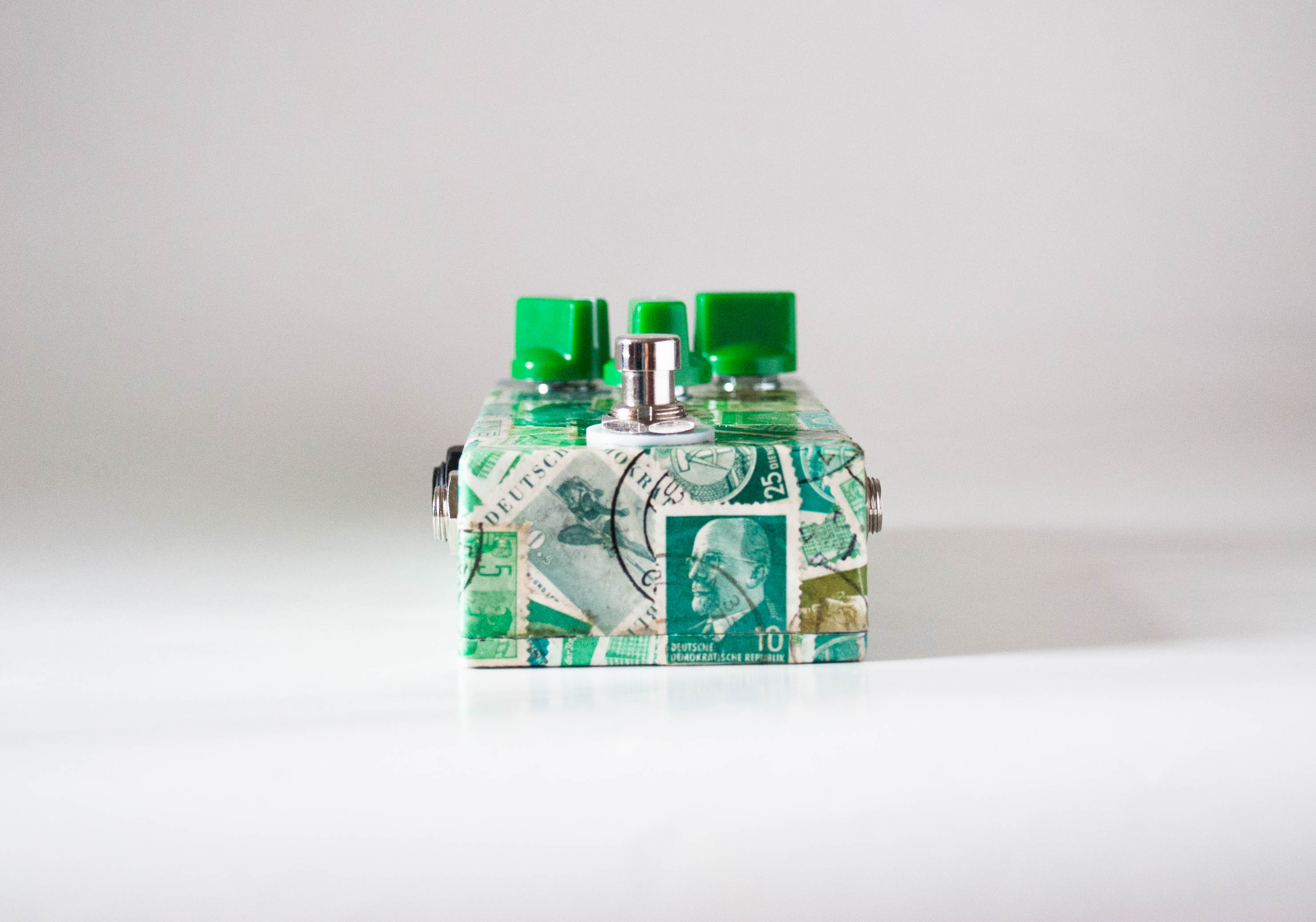
Bottom side view of the Green Tremolo

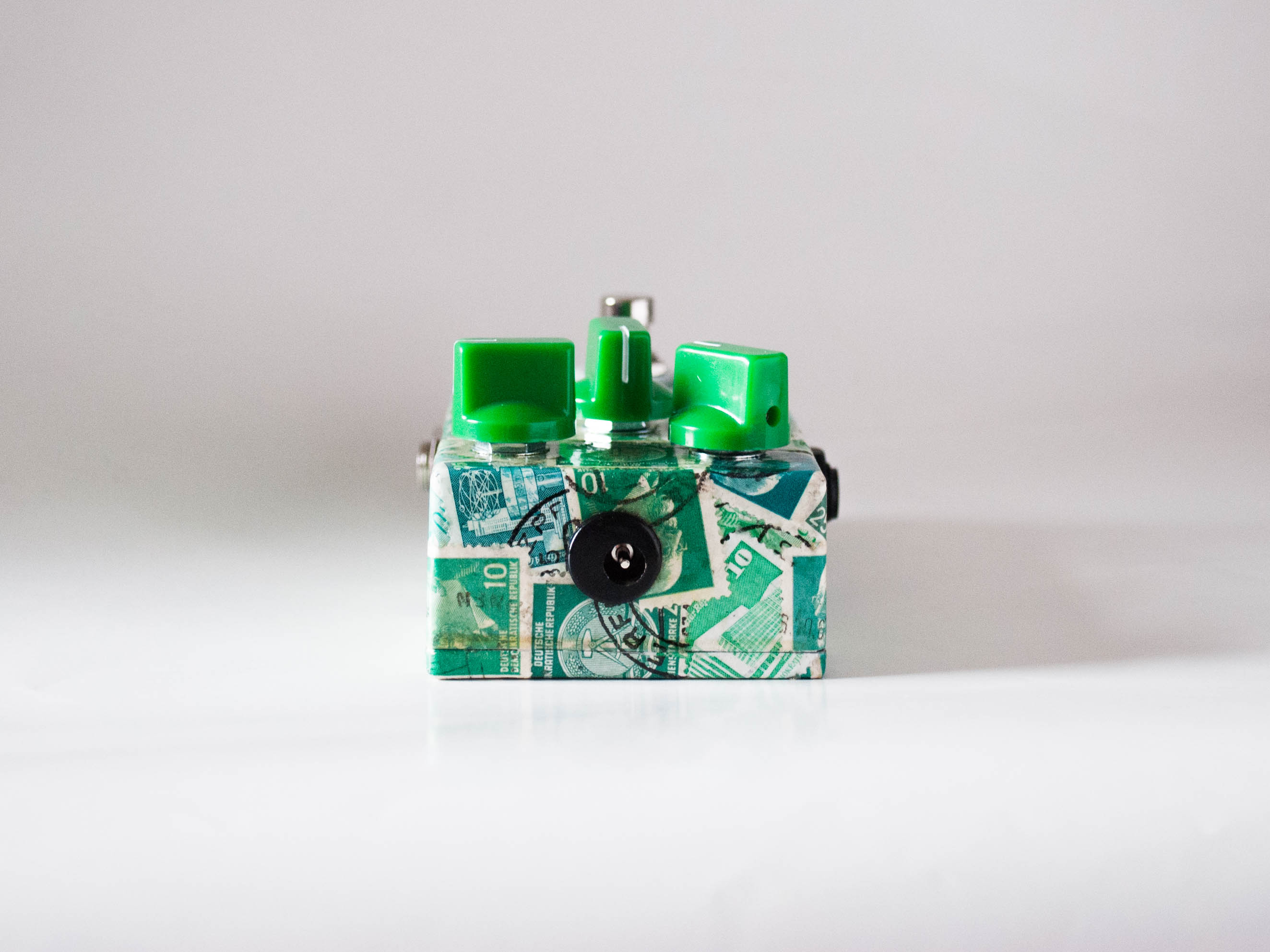
Right side view, showing the input
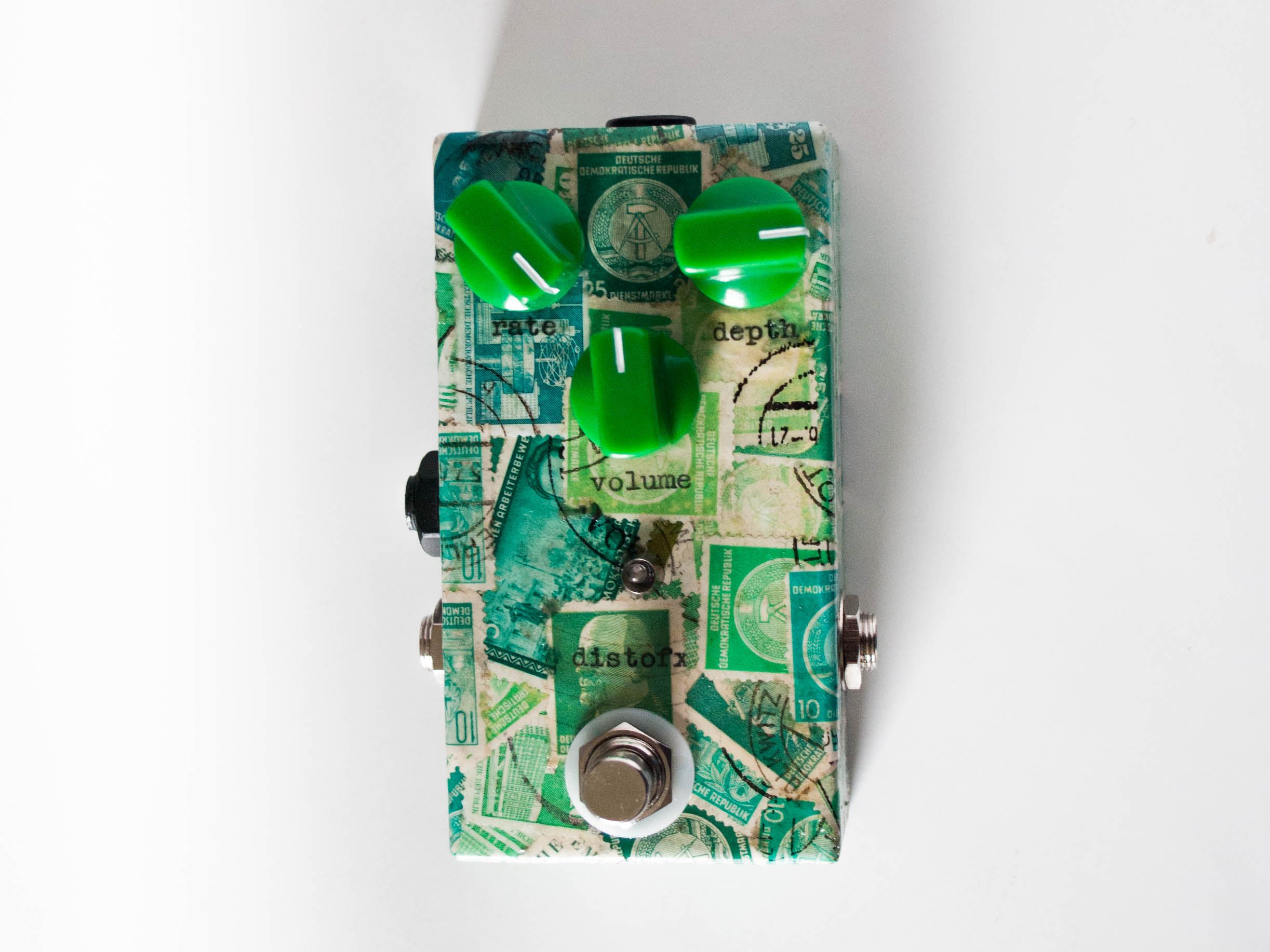
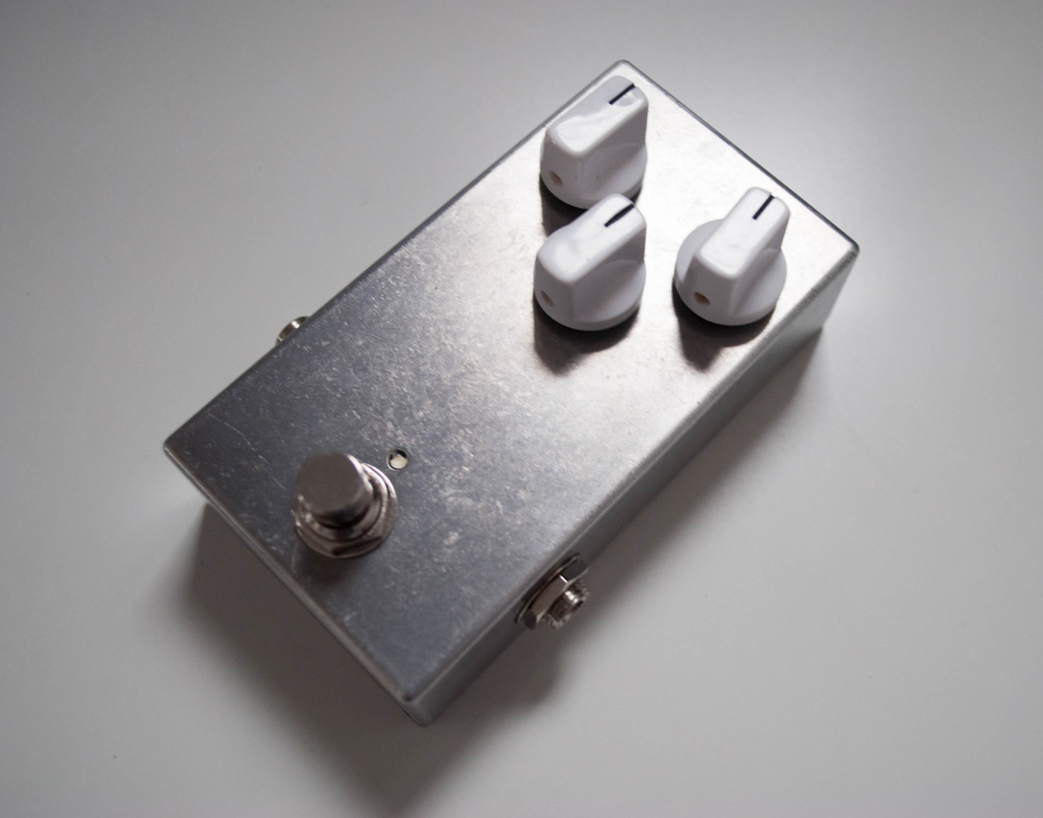
Top side view of the Green Tremolo

Bottom view of the Green Tremolo
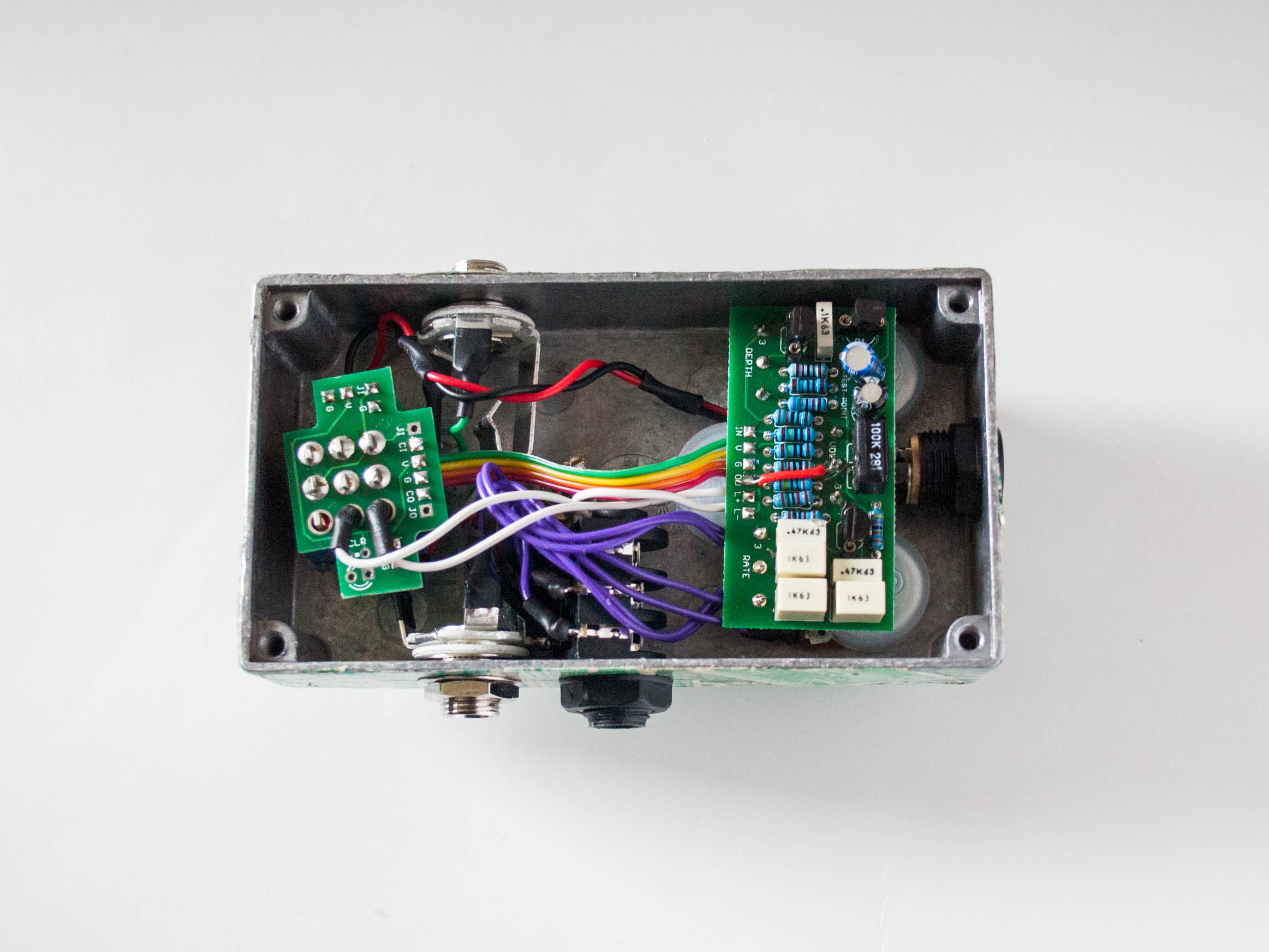
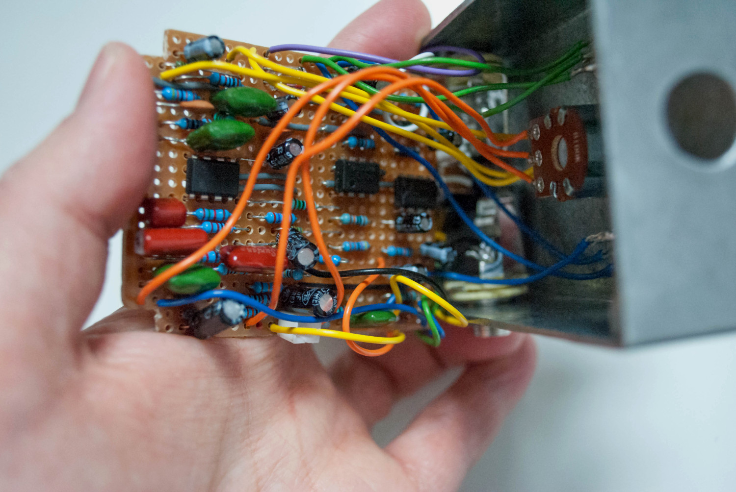
Inside view of the Green Tremolo

Part way through covering the Green Tremolo
I built this tremolo a while ago but only got around to finishing it off this week. I have done a few stamp pedals in the past, I really like the effect and find each stamp interesting. I always like to think one of them is worth a lot of money and I just stuck to a pedal. It’s quite a labour intensive process and it takes quite a few layers of clear coat to protect the surface, which often leads to a slight discolouration. However, I think this adds to the pedal and makes it look slight aged. All the stamp are East Germany era stamps. I have added labels written using a type writer.
The pedal is a Fuzz dog EA tremolo which I have adapted to allow an external rate control. The LEDs (a lovely emerald green) blinks with the speed of the tremolo with some modifications to the 3PDT daughter board.
Pedal Screen Printing
Posted on June 15th, 2015
This weekend I finished off a couple of enclosures. I used a plastic thermofax screen to print designs onto pedal and I was really pleased with the results.
This type of screen is normally used for fabric printing, but I was impressed with the result. When printing on fabric an extender is often used to thin fabric inks and allow them to pass through the screens. I did experiments with fabric inks and acrylic paints and came to the conclusion that adding extender caused the ink to smear and bleed. Normally would be absorbed into the fabric. I found the using acrylic paints without any extender I was able to minimise the ink smearing.

DIY Volume Pedal (Updated)
Posted on May 2nd, 2015
I finally built my ‘drop-in’ DIY volume pedal circuit. The circuit can be plugged directly into a Dunlop Cry Baby. However, the potentiometer in wah pedals uses a different taper, ICAR I believe. Because of the way the human ear responds to sound a logarithmic or audio taper is preferred but existing wah pots will work.
I have included a circuit a strip/vero board layout.
(more…)
DIY Volume pedal
Posted on April 26th, 2015
A couple of the wires on my wah had broken so I needed to re-wire it. Recently I had been thinking about modifying the wah into a three in one wah/volume/expression pedal. Since I had to re-wire it anyway I took the opportunity to build a volume pedal.
I put together a circuit with a simple buffer, using the wah pot as a volume. I also added a DPDT toggle switch to bypass the buffer.
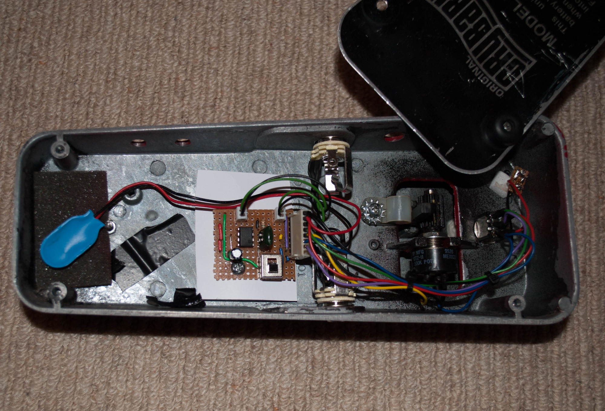
The circuit needs a bit more work. Currently with the toe down the signal is quietest and with the heel down the signal is loudest. It feel better if the volume operation was inverted.
The White Klon
Posted on February 28th, 2015
So I wanted to see what all the fuss for the Klon was about. This was the first pedal I have built for a while. I didn’t want to buy or etch a PCB and I kept finding links to tagboardeffects so I bought the components and set to work over the New Year.
The vero board layout mentioned that it might be a squeeze to get the layout inside a 1590B so I took that as a challenge. I ended up using a Hammond Eddystone enclosure which is slightly smaller than a 1590B so I was glad I managed it.
I kept a white colour scheme using white knobs and DC jack along with an ultra-bright white LED.
Since space was limited a 3PDT might not have fitted. I liked how I had mounted the LED to the footswitch when I built my prototype pedal. So I mounted the LED and a millennium bypass circuit to the DPDT footswitch.
Prototype
Posted on August 27th, 2014
When I’m building pedals, I often start by trying circuits out on a breadboard. One thing I have always struggled with is off-board components. One option is to add plug potentiometers directly into the breadboard but I often find the components don’t stay in the breadboard. The second option is to wire the off-board components up but I find this a bit messy.
A few years ago I saw the ZVex Inventobox. The idea was to create a pedal that would allow people to experiment. So inspired by this pedal I decided to come up with my own design.
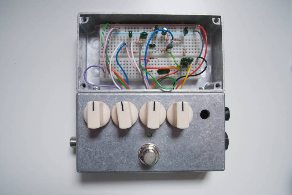
The enclosure is built using two Hammond 1590B enclosures. All the potentiometers, switches and jacks are located in the bottom half of the enclosure with a breadboard located in the upper half of the enclosure. The bottom half of the enclosure can be access through holes in between the two halves. The footswitch is a DPDT switch with a GeoFex millennium bypass. (more…)
Disto Noise Gate
Posted on July 11th, 2009
This is an idea I’ve been playing with for a while, this quick video shows the trigger stage of the noise gate. The gate ‘open/close’ is indicated by LEDs. The trigger circuit needs some adjustments but is working fairly well.
PT-80 Delay self-oscillating
Posted on May 16th, 2009
This video was made upon request and demonstrates the PT-80 delay self-oscillating and going into feedback.


